nextnano3 - Tutorial
next generation 3D nano device simulator
3D Tutorial
Strain effects in freestanding three-dimensional nitride nanostructures
Author:
Stefan Birner, M.
Povolotskyi
If you want to obtain the input files that are used within this tutorial, please
check if you can find them in the installation directory.
If you cannot find them, please submit a
Support Ticket.
-> 3DGaNAlGaN_QW_strain_freestanding_nn3.in - input file for the nextnano3 software
-> 3DGaNAlGaN_QW_strain_freestanding_nnp.in -
Strain effects in freestanding three-dimensional nitride nanostructures
-> 3DGaNAlGaN_QW_strain_freestanding_nn3.in
In this tutorial, we study the strain in lattice mismatched three-dimensional
freestanding heterostructures of wurtzite crystal structure.
The calculated strain pattern of this AlGaN/GaN nanowire is found to be highly
nonhomogeneous.
The elastic energy has been minimized using continuum elasticity theory.
We assume that the external stress applied to the structure is zero
(freestanding structure).
This tutorial is based on the following paper:
[Povolotskyi]
Strain effects in freestanding three-dimensional nitride nanostructures
M. Povolotskyi, M. Auf der Maur, A. Di Carlo
physica status solidi (c) 2, 3891 (2005)
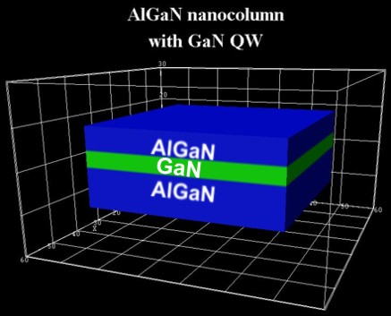
The following figure shows the AlGaN /
GaN / AlGaN quantum well
structure.
A 4 nm wide GaN QW layer is embedded between
two Al0.28Ga0.72N
layers.
The bottom AlGaN layer has a width of 10 nm,
the top AlGaN layer has a width of 6 nm.
The overall shape of this nitride nanowire structure has the form of a cuboid
with 50 nm x 50 nm extensions in the x and y directions.
The height in the z direction is 20 nm.
The overall structure is surrounded by air (i.e. with a material where
all elastic constants are zero).
The material interfaces are perpendicular to the hexagonal c axis of the
wurtzite lattice, i.e. perpendicular to the [0001] crystallographic direction.
The QW is grown along the [0001] direction (z direction).
$domain-coordinates


 ...


 hkil-x-direction =  1  0 -1  0
!
x axis of simulation coordinate system
! hkil-y-direction = -1 2 -1 0 !
 hkil-z-direction =  0  0  0  1
!
Freestanding structure
  $simulation-flow-control

   ...

   strain-calculation =
strain-minimization-new  !
strain
routine necessary for freestanding structure
$strain-minimization-model
!
for strain-calculation =
strain-minimization
...
grown-on-substrate =
no !
freestanding structure
 ! grown-on-substrate       =
yes      !
thick
substrate (default) - not used in this tutorial!
Results
Strain tensor components of the freestanding nitride heterostructure
The following figures show the strain tensor components eij(x,y,z) as
a function of coordinates (x,y,z) of slices through the structure where x =
constant (vertical cross section of the structure).
The slices are perpendicular to the x direction [1 0 -1 0] and are positioned in
the center of the structure.
Note that GaN has a larger lattice constant than AlGaN.
Consequently, we expect the GaN layer to be compressively strained and
the AlGaN layers to be tensilely strained (or rather unstrained).
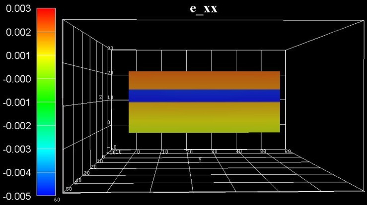
The following figure shows the strain tensor component exx.
==> strain1/e_sim_xx3D.fld / *.coord / *.dat
The bottom AlGaN layer is rather unstrained (at the bottom), the GaN QW layer is
strained compressively along the x direction (blue
region).
This is not a surprise as we assumed coherent interfaces, i.e. the atomic planes
match each other perfectly (pseudomorphic strain).
The GaN QW induces a tensile strain to the AlGaN top layer (red
region).
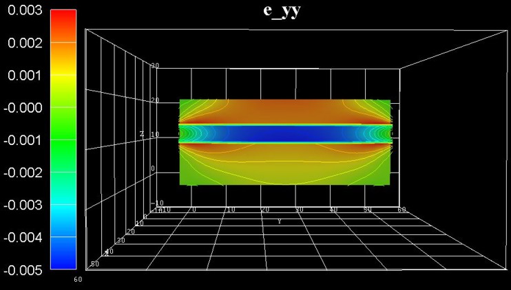
The following figure shows the strain tensor component eyy.
Similar to the figure for the exx component, the GaN layer is
compressively strained (blue region) but
only in the center and not at the boundaries where it is nearly relaxed.
Note that the exx and eyy strain tensor components are not
symmetric. This is due to the nitride crystal structure which has hexagonal
symmetry perpendicular to the (x,y) plane (and not cubic symmetry as the
geometry of the structure).
- In the center (blue region),
the GaN takes on the lattice constant of AlGaN (compressive strain).
- At the QW boundaries, the GaN takes on the lattice constant of
~GaN (nearly fully relaxed).
- Below and above the QW boundaries (red
regions), the AlGaN takes on the lattice constant of ~GaN (tensile strain).
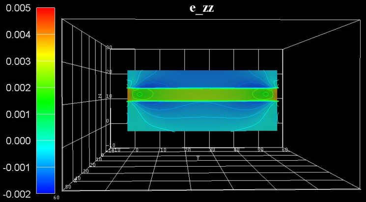
The following figure shows the strain tensor component ezz.
As the GaN layer is compressively strained along both the x and y directions,
it is tensilely strained (green region)
along the z direction (biaxially strained GaN layer, Poisson ratio).
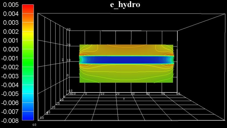
The following figure shows the hydrostatic strain ehydro = exx
+ eyy + ezz which is the trace of the strain tensor,
i.e. the sum of the diagonal strain tensor components. It corresponds to the
overall volume change.
==> strain1/e_hydro3D.fld / *.coord / *.dat
The blue region indicates that the GaN is
strained compressively.
AlGaN is mostly unstrained apart from the red
regions at the left and right boundaries of the material interfaces.
In a real sample, due to the deformation, the heterostructure changes its shape
and becomes bended.
In our case, the strain is small (less than 1%), so the shape of the structure
does not change significantly.
In contrast to heterostructures which are infinitely large and homogeneous in
the lateral directions (i.e. in the (x,y) plane), the deformation of a structure
of a finite size is not homogeneous, as e.g. in GaN nanowire heterostructures.
Since the structure is grown along the high symmetry direction [0001], the
strain patterns exhibits reflection symmetry along the axis through the center
(oriented parallel to the z axis).
The deformation becomes homogeneous in the region near the central axis,
reproducing the case of an infinitely large structure.
The following figure shows the offdiagonal strain tensor component eyz.
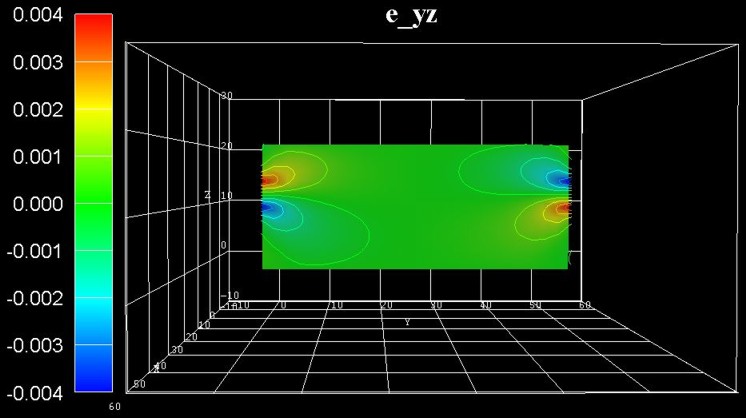
The strain tensor components exy and exz are zero for this
particular slice.
(In fact, the maximum value of exy is an order of magnitude smaller
that the maximum value of exz or eyz.)
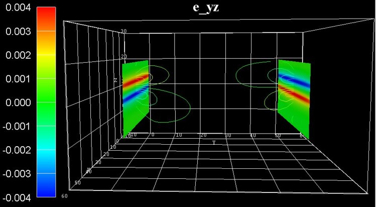
The following figure shows the same offdiagonal strain tensor component eyz
but this time at slices at the left and right boundaries.
Due to a possible usage of such structures as a light emitter, the strain in the
GaN layer where charge carriers are confined, is or particular interest, i.e.
the influence of stain on the conduction and valence band structure through
deformation potentials.
Additionaly, piezoelectric and pyroelectric fields have to be taken into
account.
The piezoelectric fields depend on the strain distribution in the sample.
Thus both the piezoelectric field and the GaN energy gap will vary along the
lateral direction.
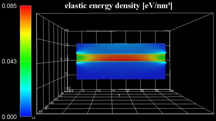
This figure shows the energy density of the elastic deformation in units of
[eV/nm3].
The accumulated elastic energy in the pseudomorphically grown GaN QW is
gradually reduced towards the free surface along the lateral direction.
Consequently, the GaN QW center is almost fully strained, whereas towards the
lateral surface there is a continous relaxation.
==> strain1/ElasticEnergyDensity3D_eV.fld / *.coord / *.dat
These figures are part of the output, i.e. 2D slices of the 3D data. This can be
done as follows:
	!---------------------------------------------------------------------------!

	$output-section !

	section-number = 1   section-name =
	slice_middle_along
	section-type = z   x =
	25.0 y = 25.0 !
1D slice through center along z axis
	section-number = 2   section-name =
	slice_middle_parallel_QW_plane
	section-type = xy  z =
	12.0
	!
	section-number = 3   section-name =
	slice_middle_perp_QW_plane
	section-type = yz  x =
	25.0
	!
	section-number = 4   section-name =
	slice_boundary_perp_QW_plane
	section-type = xz  y =
	2.0
	!
	$end_output-section
	!

	!---------------------------------------------------------------------------!
Similar figures can also be found in these papers:
-
Columnar AlGaN/GaN Nanocavities with AlN/GaN Bragg Reflectors Grown by
Molecular Beam Epitaxy on Si(111)
J. Ristić, E. Calleja, A. Trampert, S. Fernández-Garrido, C. Rivera, U.
Jahn, K. H. Ploog
Phys. Rev. Lett. 94, 146102 (2005)
-
Carrier-confinement effects in nanocolumnar GaN∕AlxGa1−xN quantum disks
grown by molecular-beam epitaxy
J. Ristić, C. Rivera, E. Calleja, S. Fernández-Garrido, M. Povoloskyi, A. Di
Carlo
Phys. Rev. B 72, 085330 (2005)
-
Strain-confinement mechanism in mesoscopic quantum disks based on
piezoelectric materials
C. Rivera, U. Jahn, T. Flissikowski, J. L. Pau, E. Muñoz, and H. T. Grahn
Phys. Rev. B 75, 045316 (2007)
|